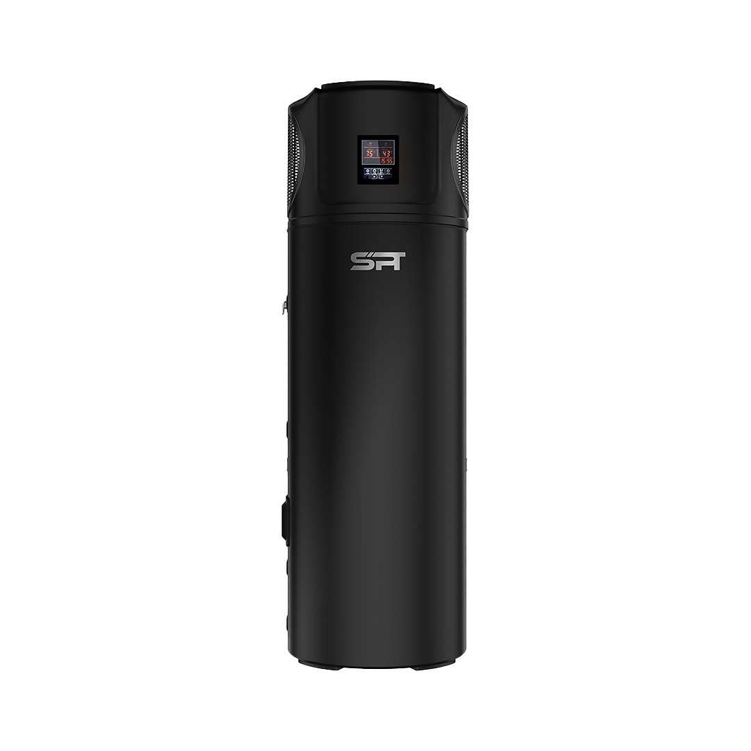
SPT DARK KNIGHT
USER MANUAL
- RESIDENTIAL
- WH265A-R | WH265A-RE
- WH315A-R | WH315A-RE
- COMMERCIAL
- WH265A-C | WH265A-CE
- WH315A-C | WH315A-E
SAFETY INFORMATION
Before you begin
- Read First, Install Later: This manual contains crucial instructions for safe installation and operation. Please thoroughly read this entire manual before attempting any work on your heat pump water heater. Keep it handy for future reference.
- Authorised Personnel Only: Installation, commissioning, and servicing of this heat pump must be completed by a qualified a
Electrical Safety
- Danger: Live Wires! Accessing internal components exposes 240V wiring. Only authorized personnel should remove access covers for work.
- Damaged Power Supply? Don’t Touch! If the power cord is damaged, do not touch it. Contact a qualified technician for replacement to avoid potential hazards.
- Wet Hands are No Match for Electricity: Always handle power connections and plugs with dry hands to prevent electrical shock.
- Supervision Required: This appliance is not intended for unsupervised use by children or individuals with limited physical, sensory, or mental capabilities. Supervise children to ensure they do not play near the heat pump.
General Safety Precautions
- Hot Water, Hot Pipes: Be cautious when touching pipes, as they may be hot.
- Clear the Area: Do not place objects on or against the heat pump.
- Flammable Materials? Keep Them Away: Store no chemicals or flammable materials near your heat pump to avoid fire hazards.
- Full Water Tank is Essential: Do not activate the heat pump unless the water tank is completely full.
- Earthing is Essential: Your home’s electrical system must have a proper earth connection for safe operation.
- Residual Current Device (RCD): Ensure your heat pump is protected with an appropriately rated RCD to prevent electrical hazards.
- Warning Labels Matter: Do not tamper with any warning labels or instructions on the heat pump’s exterior.
Professional Support is Key
- Qualified Installation: A qualified professional experienced in both mechanical and electrical systems should install your heat pump.
- Local Wiring Regulations: Always adhere to local wiring regulations during installation.
- Relocation Requires Expertise: Moving your heat pump requires a qualified professional to ensure safety.
- Maintenance by Professionals: Only trained and qualified personnel should perform maintenance or repairs on your heat pump.
- Electrical Connection: The electrical connection should be via a 20A RCD/MCB or RCBO with a test button function.
Safety with Refrigerant (R290 Propane)
- Flammable Gas Alert! This appliance uses R290 (propane), a flammable gas classified as Class 3 according to AS 1677. Only a qualified refrigeration mechanic with an appropriate Australian refrigerant handling license can handle it.
- Fire Risk – Leak Detection: If you suspect a refrigerant leak, turn off the unit at the mains and contact a service agent immediately. Leaks combined with ignition sources can be dangerous.
- Storage and Transportation: Follow regulations for storing, transporting, and handling hazardous goods like flammable gases.
Additional Warnings
- Children and Wet Environments: This appliance is not suitable for use in wet rooms like bathrooms unless housed in a separate cupboard.
- Never Use Flammable Sprays: Avoid using flammable sprays like hairspray or paint near the unit to prevent fire hazards.
- End-of-Life Recycling: Only a qualified professional can safely remove and dispose of the refrigerant.
- Hydrogen Gas Buildup: If the hot water system is unused for two weeks, highly flammable hydrogen gas may accumulate inside. To dissipate it safely, turn on a hot tap for several minutes until the gas discharge stops. Use a sink or bathtub outlet, not dishwashers or washing machines. During this process, avoid smoking, using open flames, or operating electrical appliances nearby.
Symbols and their Meanings
This manual uses safety symbols to emphasize important safety precautions. Please understand their meaning:
- CAUTION: Indicates a potential for minor or moderate injury if the precaution is not followed.
- WARNING: Warns of serious injury or death if the warning is ignored.
- DANGER: Indicates a situation that will result in death or serious injury if not avoided.
Following these safety guidelines will ensure the safe and efficient operation of your heat pump water heater. If you have any questions or concerns, please consult a qualified professional.
MAINTENANCE
Regular Maintenance Tips
- Check Connections: Regularly inspect the power cord, plug, and ground connection for any damage or loose connections.
- Protect Against Freezing: In extremely cold climates, drain the water tank to prevent freezing and damage.
- Clean the Tank and Heater: Schedule a professional cleaning of the inner tank and boost electric heater every six months to maintain efficiency.
- Anode Rod Inspection: Check the anode rod every six months and replace it if necessary.
- Lower Temperature Settings: Reduce energy consumption by setting a slightly lower water temperature if your hot water needs are moderate.
- Proper Shutdowns: When not using the heat pump for extended periods, turn off the power, drain the water tank, and close all valves.
- Pressure Relief Valve Maintenance: Regularly check and maintain the pressure relief valve (PTR) according to manufacturer’s instructions.
By following these guidelines, you can help ensure the long-term performance and efficiency of your heat pump.
Anode Rod Maintenance
Anode Rod Importance: The anode rod helps protect your water heater from corrosion. Regular inspection and replacement are essential for maintaining your unit’s efficiency and lifespan.
Professional Installation Recommended:
While it’s possible to replace the anode rod yourself, it’s recommended to hire a qualified plumber for this task. They have the necessary expertise and tools to ensure the job is done correctly.
Key Steps Involved (for informational purposes only):
- Turn off the power and water supply to the unit.
Drain the water tank completely. - Access the anode rod by removing the top panel.
Replace the old anode rod with a new one, ensuring a secure seal. - Refill the water tank and restore power.
Remember: Incorrect installation can lead to damage or safety issues. It’s best to leave this task to a professional.
System Operation
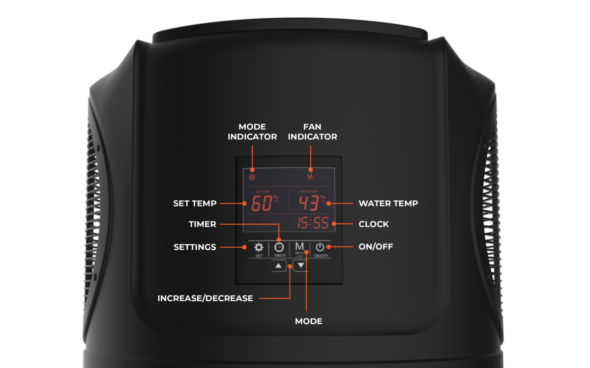
Heat pump mode
Fast heating mode
Electric heater mode
Defrost mode
Fan indication
Lock indication
Timer ON
Timer OFF
TURNING THE SYSTEM ON/OFF
Turning the system ON/OFF
To turn the system OFF: While the unit is running, press and hold the ON/OFF button for 2 seconds to power off.
CHANGING MODES
Changing Modes
PLEASE NOTE: This function is unavailable for models without electric heating.
LOCK FUNCTION
Lock Function
To Unlock the unit: Press and hold the MODE again for 3 seconds. The lock function will now be cancelled and all buttons unlocked.
CLOCK & TIMER
Setting the Clock
Setting the ON/OFF Timer
WIFI SET UP
STEP 1 - Download the Application
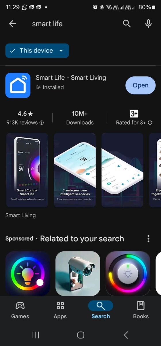
Search the “Smart Life – Smart Living” app in your Google Play or Apple App Store

STEP 2 - Activate Pairing Mode
1. Go to the display screen on your Dark Knight System and 2. Press and hold the mode button (M) and the Up Arrow until the Wi-Fi Symbol starts flashing to enter pairing mode

STEP 3 - Add Device
1. Open the Smart Life App and press Add Device
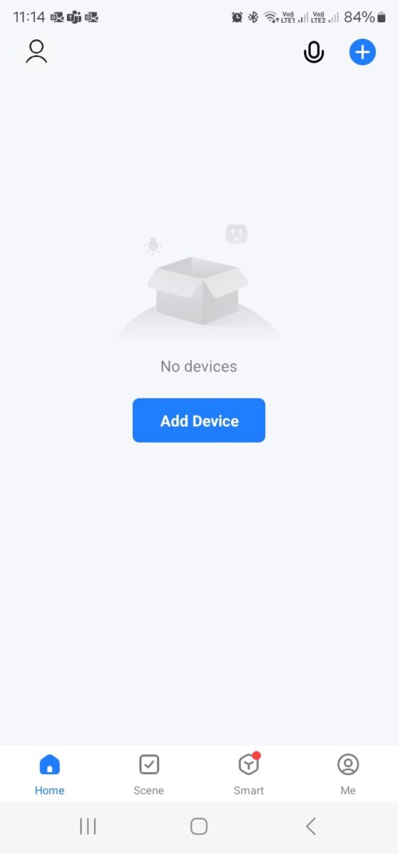
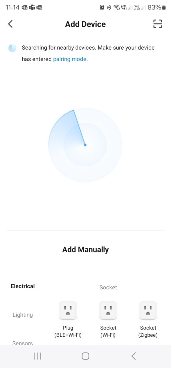
STEP 3 - Cont.
2. Once the device is found, press on the device to add it
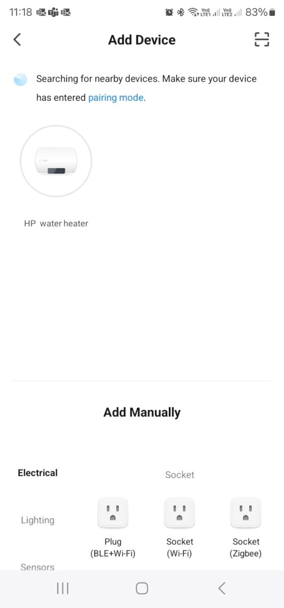
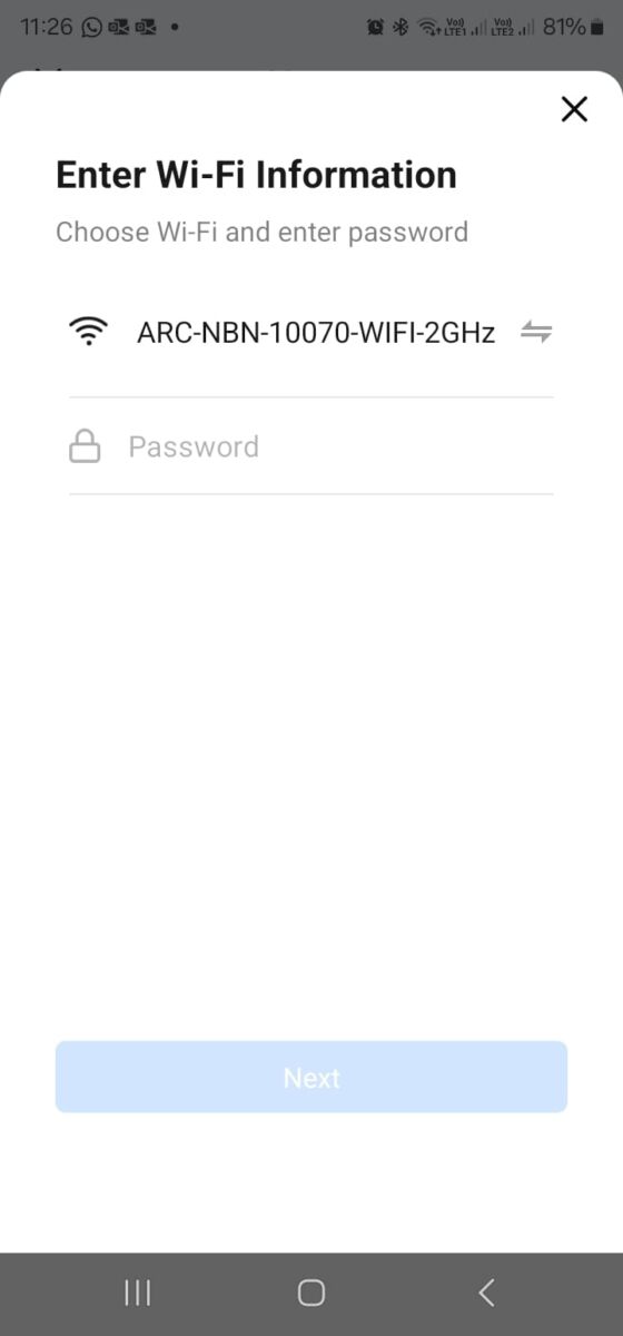
STEP 3 - Cont.
3. Enter your Wi-Fi password
STEP 3 - Final Steps
4. Wait for the device to be downloaded! Woohoo you are all set up
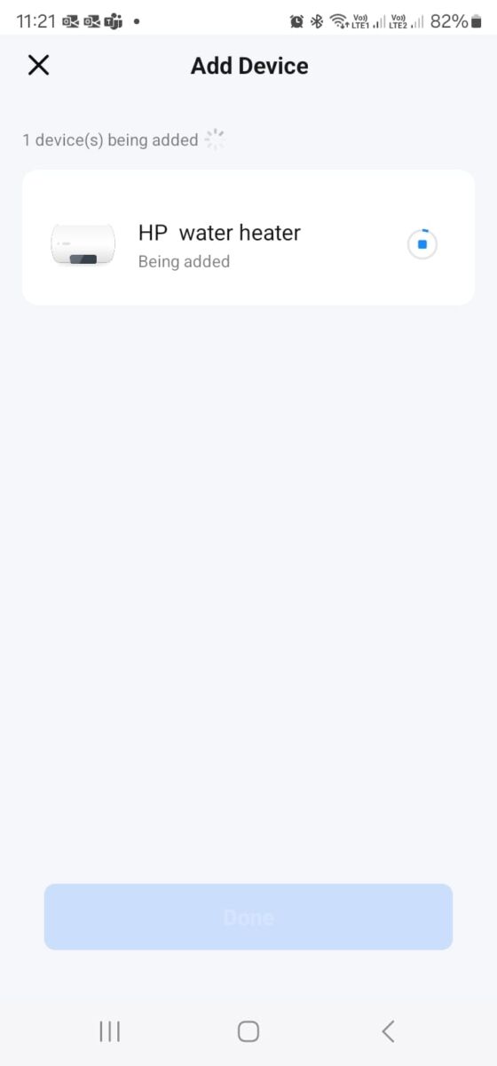
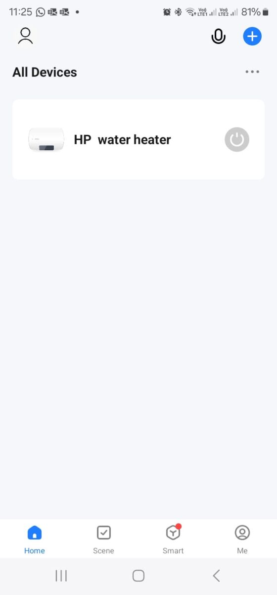
Application Functions
Turn System On / Off When the system is turned off, it automatically enters standby mode. In standby mode only essential maintenance functions (like Legionella sanitisation) are active, ensuring that the water remains safe without fully powering the system.
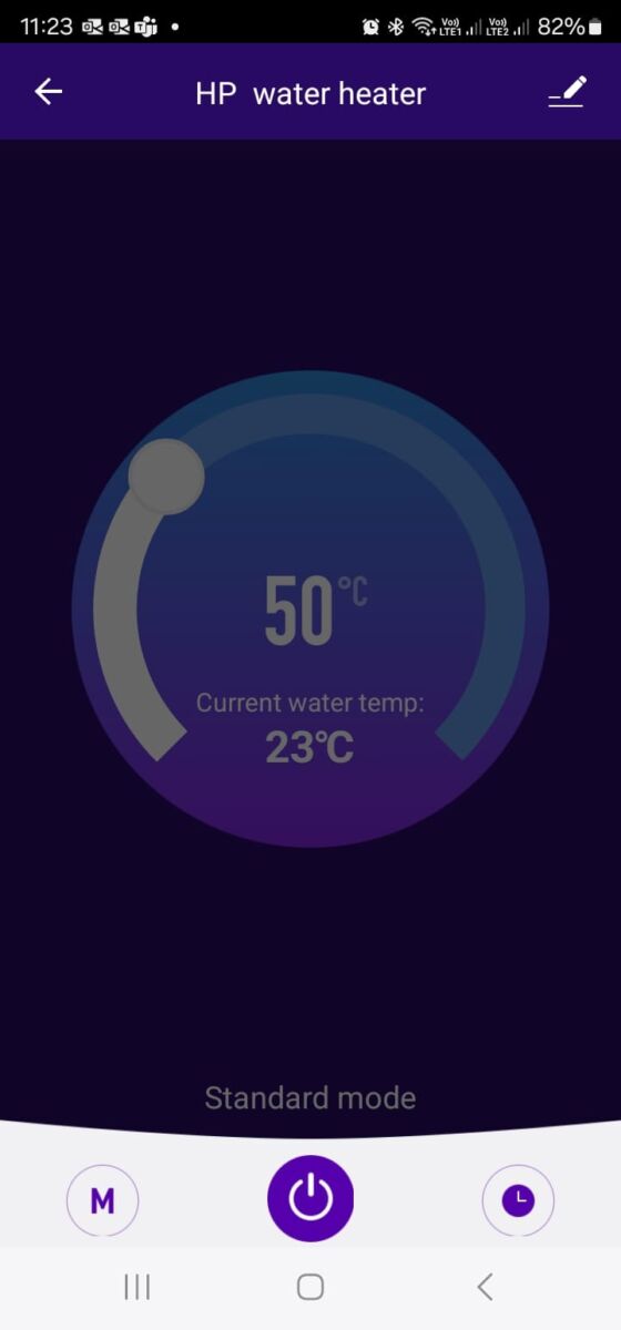
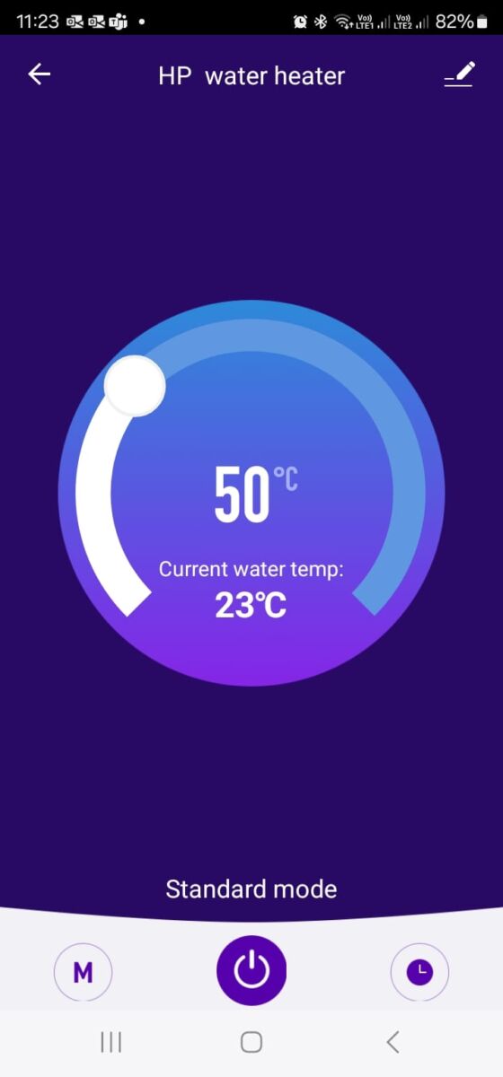
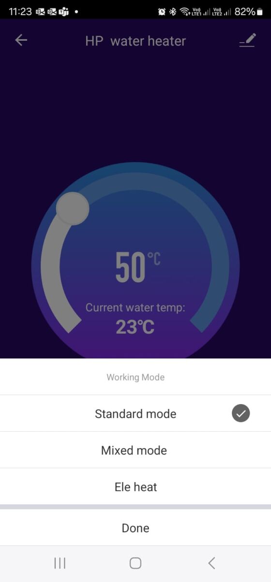
Changing the Mode
There are three (3) operating modes to choose from: 1. Standard Mode: An eco-friendly mode where only the heat pump operates to heat your water. 2. Mixed Mode: (available only on RE models) A hybrid mode where the heat pump primarily heats your water, but an electric element will assist during high-demand periods or in colder climates to ensure consistent comfort. 3. Ele Heat Mode: (available only on RE models) An emergency backup mode, used only if the heat pump fails, where the electric element alone heats the water.
7-Day Scheduler
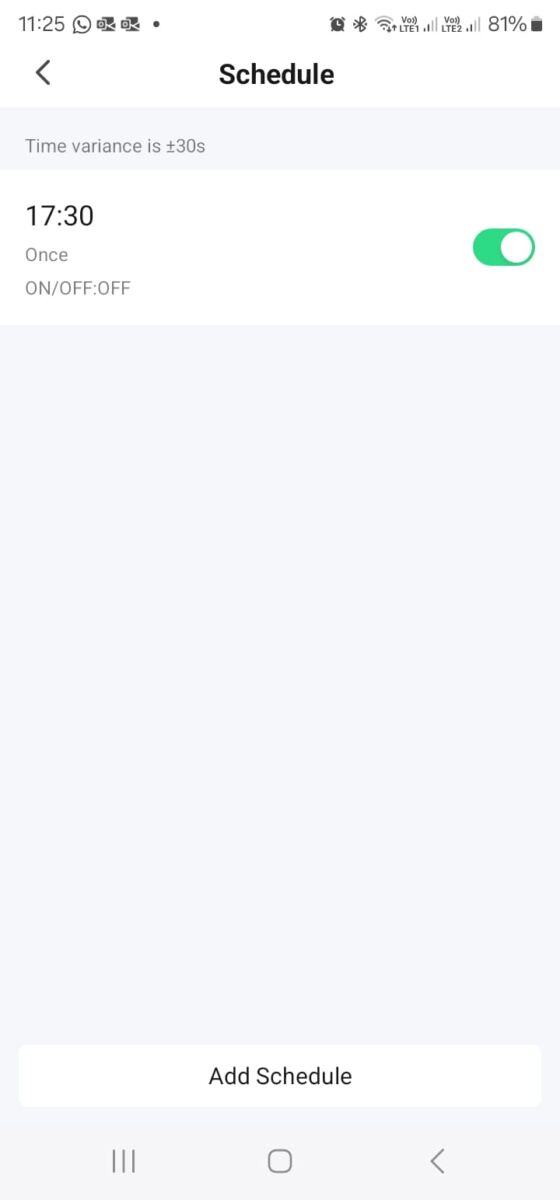
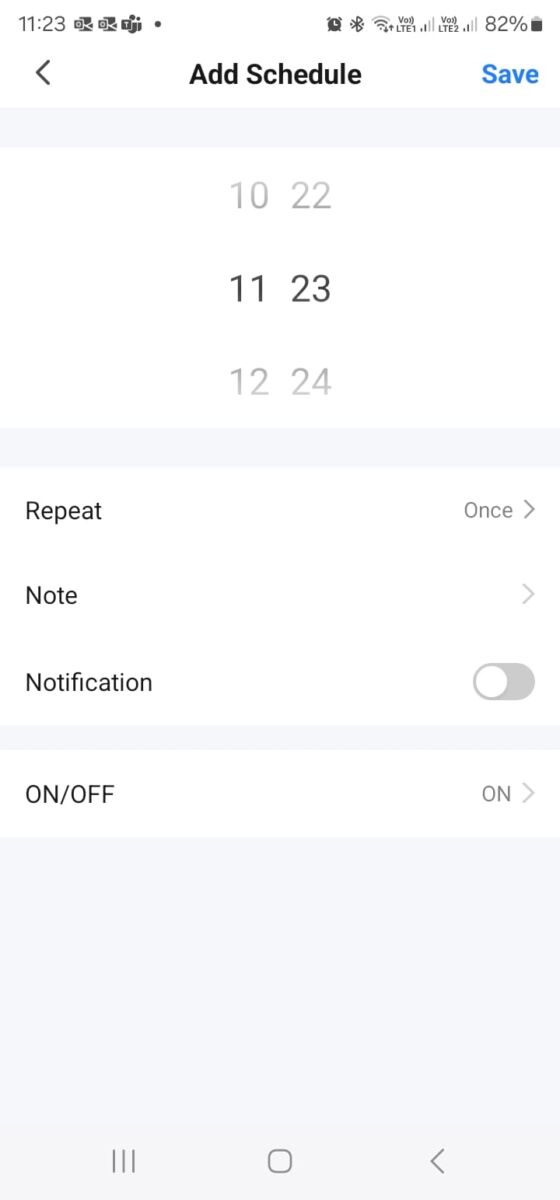
The 7-Day Scheduler allows you to set your system to turn on or off at specific times throughout the week. This feature is ideal for homes powered by solar energy, as it ensures the system operates primarily when solar power is available, maximising energy efficiency. It’s easy to set up! Press the Add button.

Select the time of day for the system to turn on or off.
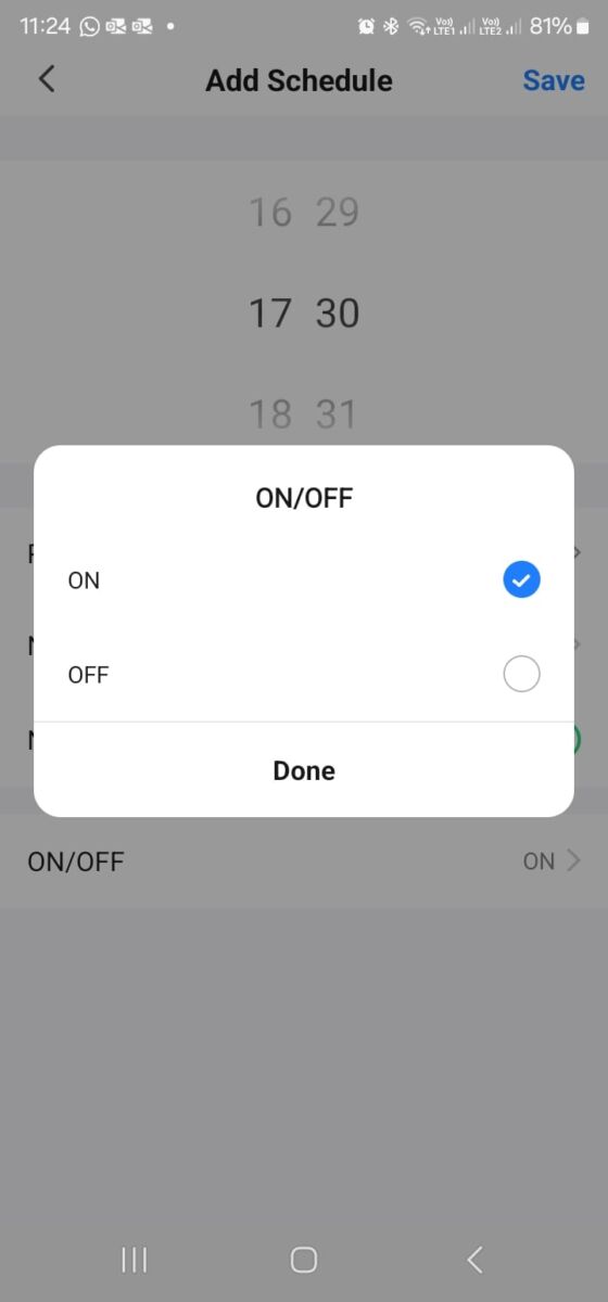
Choose the action (on or off) you want it to perform.
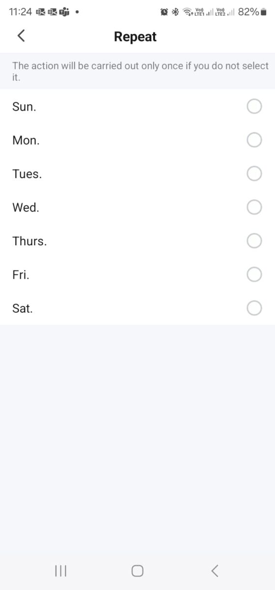
Select multiple days if you want the action repeated; otherwise, it will only be carried out once.
Enable notifications if you’d like alerts when the system turns on or off.
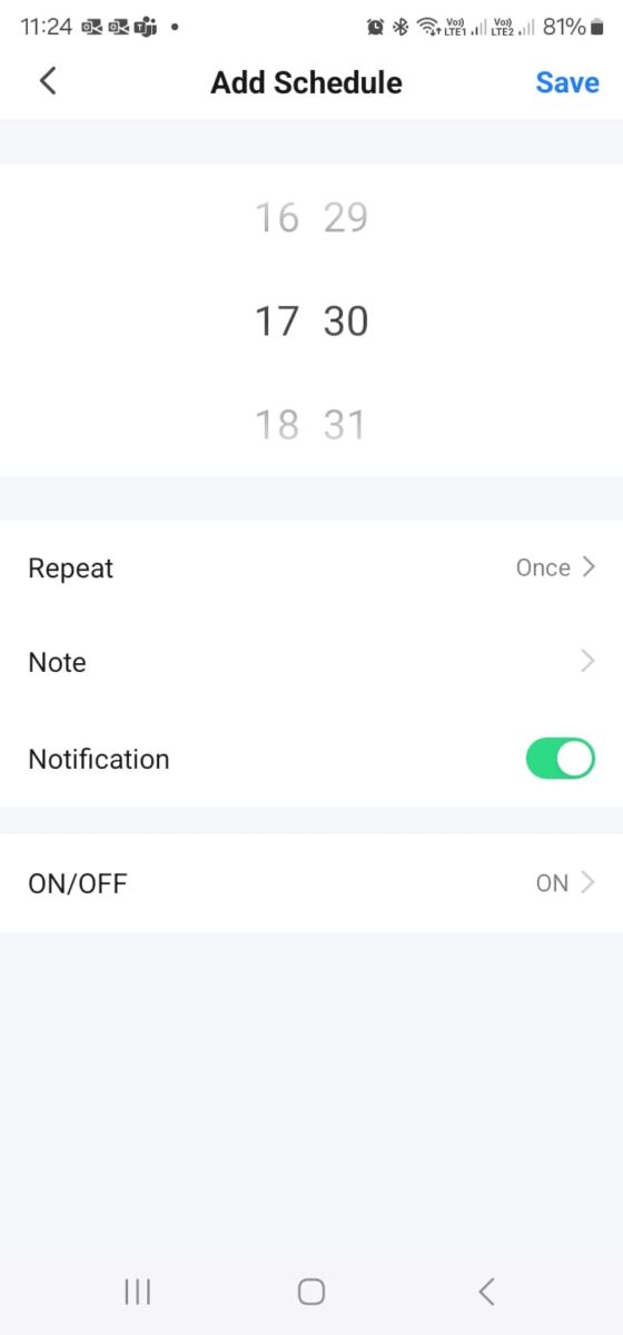
Once satisfied, press Save in the top corner.
